Tips and Tricks for Using Local Coordinate System (LCS)
When using LCS, DatuBIM
automatically brings the GCP’s to the approximate area where the images
are. Beyond that, it is the user’s
responsibility to bring the GCP’s to the exact location to allow for marking
them on images. In all cases, the goal is to mark three GCP’s in three images
each. This is the minimal requirement
that will allow you to check the accuracy of the markings you made, and in turn
generate decent hints that will allow you to geo reference your job accordingly. Once the first 3 GCP’s are marked, their
accuracy is checked, and hints are generated the process continues exactly as
done for known coordinate system except that each GCP must be marked in at
least three image and not two to be accounted for.
Tips
Tip #1 - GCP’s must be
clearly marked on the ground with their name, otherwise it would be very
difficult to handle. Marking names on
the ground is very essential especially when GCP’s are close to each other and
more than one GCP appear in the same image. Below are some examples of good markings.
Tip #3 – if no sketch is available;
acquire any information available regarding the general location of the GCP’s,
for example, on asphalt road ABC, on an intersection of XXX and YYY, on a
roundabout, on dirt, on a laid target, etc…
Tip #4 – When you first
import the GCP’s, the system starts a process of generating hint. In 90% of the cases when using local
coordinate system, no hints are generated or the generated hints are not
relevant. Therefore, it is recommend not
to wait for the hint generation by clicking the “click here” on the screen
shown below and continue your work.
Tip #5 - Do not to process flights in the same site
concurrently when using a local coordinate system.
Important Note: Once a site is set to use LCS, all flights under that site will be processed using LCS. Meaning that you cannot process your flights only using the drone’s GPS data/RTK data.
Use Cases
Now we will discuss
various use cases and how to deal with each one.
Use Case #1 - Ideal Case
Ideally, once the job is
ready for geo referencing and you import the GCP’s, the shape and size of the
distribution of both the GCP’s (Red triangle) and the images (Yellow triangle)
are similar. See the figure below.
Use Case #2 - Semi Ideal
Case
This refers to situations where the shape and size of GCP
distribution and image distribution are similar; yet, more fine-tuning of GCP
location is needed as centering them on top of each other was not good
enough. In this case, you need to use
the other tools on the “GCP MOVING TOOL”.
Look for example at this job. The
figure on the left shows the location of GCP’s after the import, and the figure
on the right shows the location of the GCP’s after centering them on top of the
images.
Sometimes, surveyors mark GCP’s in large areas, but the
images taken actually cover only part of that area. Dealing with such cases in very difficult if
you do not have a GCP sketch.
Alternatively, you can ask the surveyor to clean up the GCP file and
keep in it only GCP’s of the photographed area.
Use Case #4 – GCP Span is a zoomed in or out compared to the
image span.
After importing GCP’s to a job, they appeared as shown
below.
And now we have proper accurate hints for
the remaining GCP’s.
Tips
Tip #2 – it is always good and sometimes essential to have a sketch of GCP marking from the surveyor. Even a rough sketch could be very helpful, and it is not necessary to have all marked GCP’s on it. Even a google map with approximate locations of GCP would be a big help. See an example below.
Important Note: Once a site is set to use LCS, all flights under that site will be processed using LCS. Meaning that you cannot process your flights only using the drone’s GPS data/RTK data.
Use Cases
In this case, what you need to do is theoretically put the two triangles on top of each other. You can do this by simply opening the GCP MOVING TOOL shown below and click “To center of image” as shown below.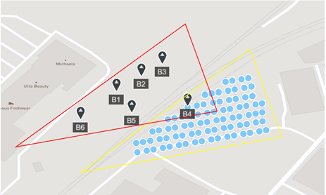
This shifts the GCP’s as shown below.
If you click now on B5 now to mark it, chances are high that you will find the GCP quickly in the closest image.
This will also be true for other GCP’s so marking three GCP’s in three images each is quick and simple.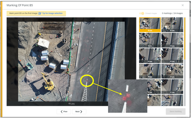
Zoom in for example to the area where P3 is.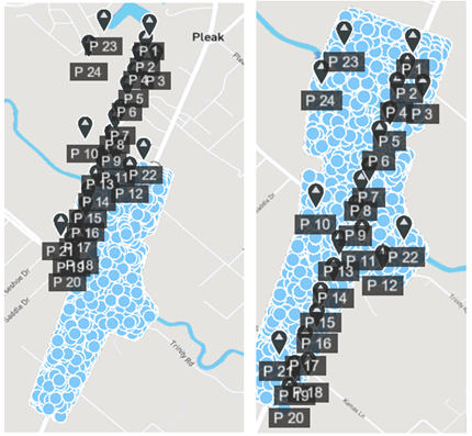
Now click on it to mark it, as you see below is in very difficult to find it in close by images.
Here is where we need to do the fine-tuning of GCP location. If we know that P2 and P4 where marked on asphalt on Road 36, and P3 was marked on Trinity Dr, then using the “GCP MOVING TOOL” we can move the GCP so P2, P3, and P4 would fall where we know they should be as shown below.
For your convenience, it is always possible to turn off the display of image location using the MAP LAYERS tool at the top right, as well as toggling between satellites and map views using the tool bar at the top left.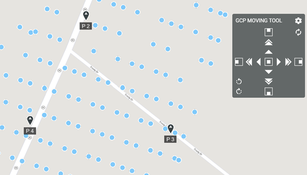
Once done moving the GCP’s click on P3 now to mark it, you will immediately see that it appears in the first or the closet image. See below.
Use Case #3 – GCP Span is a larger than image span
Assuming you do have a GCP sketch, then you need to use the “GCP MOVING TOOL” and shift the GCP’s to the right location, and then continue with marking the images.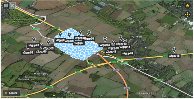
But, based on the GCP sketch this is where they were marked.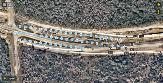
It is clear that the GCP’s are not only shifted, but they are also some sort of a zoom effect. To fix this, you need to work on each point separately to reach the minimal marking requirement. Here are the steps we did to handle this case.
- We used the “GCP MOVING TOOL” to shift the GCP’s so GCP 30 falls in the right place.
- We marked GCP 30 in three images and saved it.
- We used the “GCP MOVING TOOL” to shift the GCP’s so GCP 31 falls
in the right place.
- We marked GCP 31 in three images and saved it.
- We used the “GCP MOVING TOOL” to shift the GCP’s so GCP 42 falls
in the right place.
- We marked GCP 42 in three images and saved it.
- We ran “Check Accuracy”, here is what we got. As you see the GCP distribution changed.
Related Articles
Adding a New Site
Adding a Site The add a new site to the account, press the “+ New Site” available on the top left. Adding a new site is available only for the user defined as the Account Admin User, and the option will not appear for General Users. This will open ...Tips for a Successful Image Upload and Model Generation
The saying goes that "the output is only as good as the input." As in most data processing systems, for DatuBIM to work correctly, users need to make sure that their input data is correct from the beginning and follows best practices. This isn't ...System Requirements
DatuBIM platform is a cloud-based software and does not require a local installation on the computer. It is designed to work on commonplace office PCs and standard laptops. Operating environment requirements: Any modern OS, such as Windows, macOS, or ...Using Site Design Files (CAD Files) with DatuBIM
In this article, we will discuss and give examples on how to add site design files, how to view them, and how to use them in analysis functions. All actions related to design files are done from the Designs left tab shown below. Adding a design file ...Using Check Points
While in the process of marking GCP’s it is possible to mark any GCP as a check point using the check box next to it as shown below. Check points are marked clearly on the map. Check points should be marked in at least 2 images as the case with the ...